Chinese
 English
 Deutsch
 italiano
 español
 português
 Nederlands
 日本語
日本語 한국의
한국의




- Accueil
- >
Catégories
Produits chauds
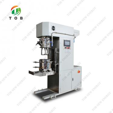
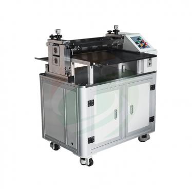
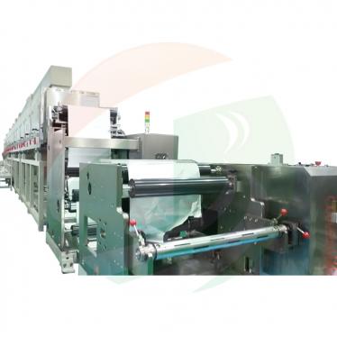
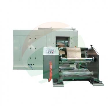
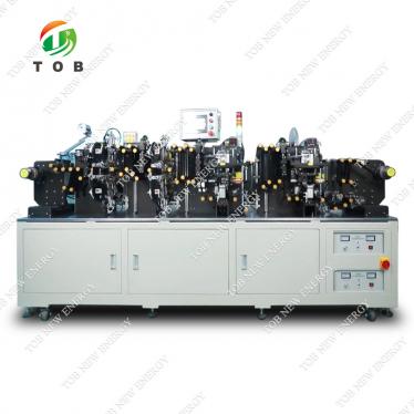
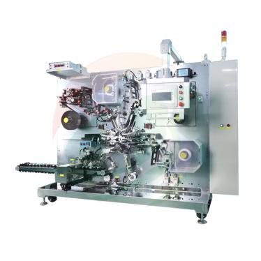
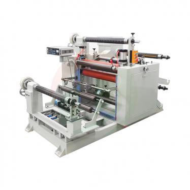
CN215429971U - Laboratory-Scale Battery Coating Machine
Sep 09,2026A complete coating line - unwinder, coating station, dryer, rewinder and an inline slurry mixer - integrated in one compact, portable housing for laboratory battery work.
Full specification and drawings: CN215429971U on Google Patents
Electrode coating sets the capacity, consistency and safety of a lithium cell: slurry must be spread evenly over the current collector and its solvent dried out, and coating quality flows directly into capacity, internal resistance, cycle life and safety. Production coaters do this well at scale - but they are large, built for batch production, and poorly suited to the coating work a laboratory actually needs.
CN215429971U, filed on 9 September 2021, answers that gap with a different geometry: instead of shrinking a production line, it packs the whole coating function - unwinder, coating station, dryer, rewinder and slurry mixer - into a single small housing that sits on a bench and can be carried.
Patent Information
| Publication number | CN215429971U |
| Title (original) | 一种基于实验室的小型电池涂布机 (Laboratory-Scale Battery Electrode Coating Machine) |
| Inventors | Huang Zhengyao (Dany Huang); Tobey Chen |
| Current assignee | XIAMEN TOB NEW ENERGY TECHNOLOGY Co., Ltd. - the registered entity of TOB NEW ENERGY |
| Filing date | 9 September 2021 |
| Document type | Utility model (kind code U) |
| Legal status | Active |
| Anticipated expiration | 9 September 2031 |
| Drawings | 6 figures |
The Production Problem This Patent Solves
The specification identifies the mismatch plainly: battery coating machines on the market are mostly used for batch production. They are large machines, and they are not suited to the coating work of a laboratory cell.
A lab researcher who needs coated electrode rolls faces an awkward choice - commit small development batches to a full-size production coater, or fall back to manual methods with poor uniformity. Neither serves the actual need: a complete, repeatable coating process on a bench-scale footprint.
The Core Approach: A Complete Coating Line in One Small Housing
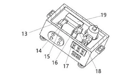
Rather than scaling a production coater down, CN215429971U re-integrates the coating process around a coating processing table inside a box housing. The web path runs: unwinder → coating station → dryer → rewinder, all inside the enclosure, with an inline slurry mixer between the unwinder and the coating station.
The mixer's delivery pipe discharges slurry exactly between the unwinder and the coating station - the shortest possible path from freshly mixed slurry to the web, so the coated material is always fed from a consistent slurry condition.
Structural Specification
Web path inside the housing
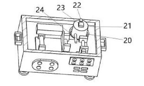
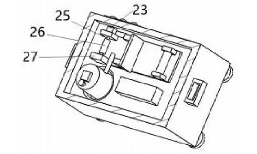
The unwinding device sits at the front end of the coating table: a motor case drives a drum via a rotating shaft to pay out the film roll. The coating device follows - a leveling roller presses slurry onto the web, and a coating brush behind it sweeps away surplus slurry that was not pressed in. The rewinder collects the coated web, and a dryer sits between the coater and the rewinder so the wet layer is cured before winding.
Inline slurry mixing with the shortest delivery path
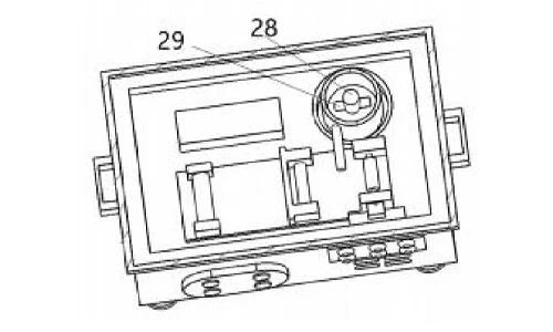
The slurry mixer is placed between the unwinding device and the coating device, seated in a recess in the housing so it cannot drift during stirring. Inside it, a stirring rod driven by a motor case through a stirring shaft mixes the coating slurry, and an inlet pipe admits raw materials. A delivery pipe carries the stirred slurry to the web - its outlet extends to the midpoint between the unwinding device and the coating device.
Compact, portable housing
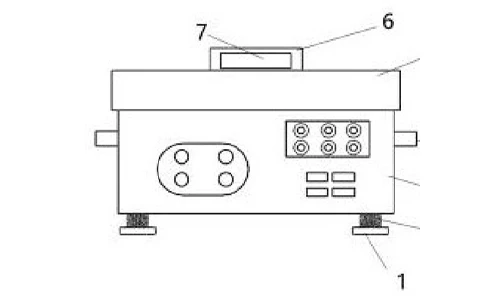
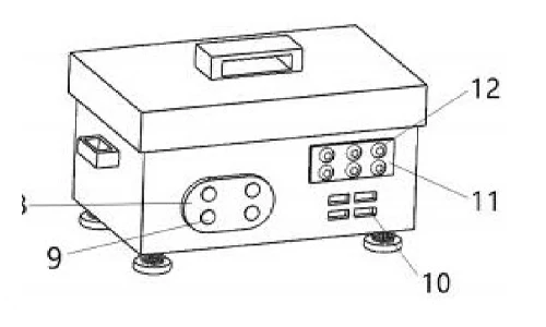
A controller on the front face governs unwinding, stirring and coating. The housing is closed by a cover with a switch handle, fitted with carrying handles on both sides for transport, and stands on support plates via connecting columns. The control panel carries an operating key, a display lamp panel and a peripheral interface.
Claimed Benefits
| Benefit | Mechanism responsible |
|---|---|
| Complete coating work in a small footprint | Unwinder, coater, dryer, rewinder and mixer integrated inside the housing |
| Consistent slurry at the point of coating | Mixer placed between unwinder and coater, delivery pipe outlet at the midpoint |
| Controlled wet layer thickness | Leveling roller pressing slurry, coating brush removing surplus |
| Cured web before rewinding | Dryer between the coating device and the rewinder |
| Portable for laboratory use | Carrying handles and compact enclosure |
How It Compares with a Conventional Coating Setup
Production coaters coat well at scale, but they are large machines built for batch output and poorly suited to laboratory battery work; the common alternative, manual coating, gives poor uniformity. This patent instead packs the complete coating path - unwinder, coating station, dryer, rewinder and an inline slurry mixer - into one compact housing that sits on a bench and can be carried.
| Dimension | Conventional approach | This patent design |
|---|---|---|
| Footprint | Full-size production coater sized for batch runs | Complete coating path inside one compact, portable housing |
| Slurry supply | Mixed remotely and transported to the coater | Inline mixer whose delivery pipe discharges at the midpoint between unwinder and coater |
| Laboratory use | Poor fit for small development batches; manual methods lack uniformity | Repeatable coating process on a bench-scale footprint |
Where This Technology Is Used Today
This patent covers the mechanical architecture of TOB's laboratory-scale electrode coating machines. The integrated design it protects - complete coating path with inline slurry mixing inside a compact housing - is how our lab coaters bring production-style coating quality to research quantities.
- Desktop Slot-Die Coating Machine
- Automatic Small-Size Coating Machine
- Lab Slot-Die Coater with 800 mm Stroke for Battery Electrode Coating
Related equipment enquiries: request a quote
Patent Drawings
Frequently Asked Questions
What does patent CN215429971U cover?
A laboratory-scale battery electrode coating machine that integrates an unwinder, a coating station with a leveling roller and a coating brush, a dryer, a rewinder and an inline slurry mixer inside a single compact housing, with the slurry delivery pipe outlet opening between the unwinder and the coating station.
Why deliver the slurry between the unwinder and the coating station?
The slurry mixer sits between the unwinder and the coating station, and its delivery pipe discharges exactly between the two. Freshly mixed slurry reaches the web over the shortest possible path, which avoids the settling and consistency drift that can occur when slurry is transported over a long distance from a remote mixer.
How does the machine control wet coating thickness?
A leveling roller presses the slurry onto the moving web, and a coating brush behind it sweeps away the surplus slurry that was not pressed in. Together they set a uniform wet layer before the web enters the dryer.
Why integrate a complete coating line in a small housing?
Conventional coating machines are built for batch production - they are large and poorly suited to laboratory battery work. Housing the unwinder, coater, dryer, rewinder and mixer in one portable enclosure lets a lab produce coated electrode rolls with a small footprint that can be carried.
Is patent CN215429971U still in force?
Yes. It is Active, filed on 9 September 2021 with anticipated expiration on 9 September 2031.
Full specification and drawings: CN215429971U on Google Patents
 abonnez-vous